
La UNI EN ISO 16090-1:2023 (tipo C ai sensi della EN ISO 12100:2010), specifica i requisiti tecnici di sicurezza e le misure di protezione per la progettazione, la costruzione e la fornitura delle macchine utensili utilizzate per il taglio a freddo di metalli e materiali non combustibili (alesatrici, fresatrici, centri di lavoro, macchine transfer e macchine speciali.
La norma non è armonizzata per la Direttiva macchine 2006/42/CE.
La UNI EN ISO 16090-1:2023 sostituisce la UNI EN ISO 16090-1:2019. Le principali novità della nuova edizione sono:
– introduzione nuove funzioni di sicurezza (Allegato J);
– modifica della MSO (modalità di funzionamento sicuro) in MO (modalità di funzionamento);
– introduzione obbligo uso di un comando di abilitazione nella modalità di funzionamento MO 3;
– aggiunta delle cabine operatore mobili.
UNI EN ISO 16090-1:2023
Sicurezza delle macchine utensili – Centri di lavoro, fresatrici, macchine transfer – Parte 1: Requisiti di sicurezza
La norma specifica i requisiti tecnici di sicurezza e le misure di protezione per la progettazione, la costruzione e la fornitura (inclusi l’installazione e lo smantellamento, le modalità di trasporto e manutenzione) di fresatrici fisse, incluse le macchine in grado di eseguire operazioni di alesatura, centri di lavoro e macchine transfer progettate per l’uso in produzione continua, che sono destinate a tagliare a freddo metalli e altri materiali non combustibili ad eccezione del legno o materiali con caratteristiche fisiche simili a quelle del legno come definito nella norma UNI EN ISO 19085-1, e vetro, pietra e materiali lapidei agglomerati come definiti nella UNI EN 14618. La norma si applica alle seguenti macchine:
a) alesatrici e fresatrici a comando manuale senza controllo numerico;
b) alesatrici e fresatrici a comando manuale con controllo numerico limitato;
c) centri di lavoro e fresatrici a controllo numerico;
d) macchine transfer e macchine per impieghi speciali;
e) macchine dotate dei seguenti dispositivi/attrezzature, i cui rischi sono stati affrontati:
– magazzino utensili;
– cambiautensili;
– meccanismi di movimentazione dei pezzi;
– meccanismo/i di bloccaggio del/dei pezzo alimentato/i;
– trasportatore/i di trucioli;
– porte ad azionamento elettrico;
– cabina/e operatore mobile/i;
– attrezzature aggiuntive per la tornitura;
– attrezzature aggiuntive per la molatura.
1. Scope
This document specifies the technical safety requirements and protective measures for the design, construction and supply (including installation and dismantling, with arrangements for transport and maintenance) of:
– milling machines (see 3.1.1), including machines capable of performing boring operations (see 3.1.2);
– machining centres; and
– transfer machines (see 3.1.3)
designed for continuous production use, which are intended to cut cold metal and other noncombustible cold materials, except wood or materials with physical characteristics similar to those of wood as defined in ISO 19085-1 and glass, stone and engineered/agglomerated materials as defined in EN 14618.
This document covers the following machines (referred to as “machines” in this document):
- manually, without numerical control, operated boring and milling machines (see 3.2.1, Group 1), e.g. knee and column type milling machines (see Figures C.1 and C.2);
- manually, with limited numerical control, operated boring and milling machines (see 3.2.2, Group 2), e.g. profile and contouring milling machines (see Figures C.3 and C.4);
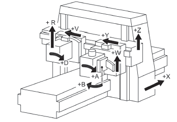
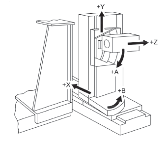
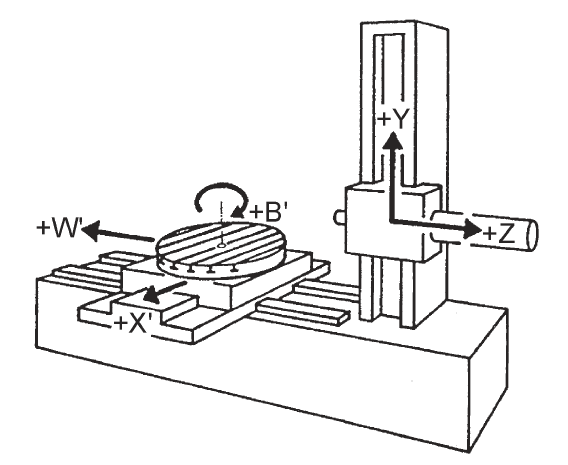
- numerically controlled milling machines and machining centres (see 3.2.3, Group 3), e.g. automatic milling machines and milling centres, e.g. multi-spindle milling machines, gear-milling machines (see Figures C.5 to C.7);
- transfer and special-purpose machines (see 3.2.4, Group 4), which are designed to process only pre-specified workpieces or limited range of similar workpieces by means of a predetermined sequence of machining operations and process parameters (see Figures C.8 to C.13).
- machines fitted with the following devices/facilities, whose hazards have been dealt with:
– tool magazine(s);
– tool changer(s);
– workpiece handling mechanism(s);
– powered workpiece clamping mechanism(s);
– swarf/chip conveyor(s);
– power-operated door(s);
– moveable operator cabin(s);
– additional equipment for turning;
– additional equipment for grinding.
This document deals with all significant hazards, hazardous situations and events relevant to this type of machinery which can occur during transportation, assembly and installation, setting, operation, cleaning and maintenance, troubleshooting, dismantling or disabling according to ISO 12100, when the machinery is used as intended and under conditions of misuse which are reasonably foreseeable by the manufacturer (see Clause 4).
This document presumes accessibility to the machine from all directions and specifies access conditions to operator positions. It also applies to workpiece transfer devices including transport devices for loading/unloading when they form an integral part of the machine.
3.2 Groups of machines
With regard to the applications and the relevant hazards, machines are subdivided into four different groups.
3.2.1 Group 1 machine: Manually controlled boring and milling machine without numerical control
machine where axis motion is controlled by actuation of a mechanical handwheel or where powered single-axis motion is controlled by mechanical, electrical or other means but without the capability for programmed multiple axes movement
Note 1 to entry: For an illustration, see Figures C.1 and C.2.
3.2.2 Group 2 machine: Manually controlled boring and milling machine with limited numerical controlled capability
machine that can be operated like a Group 1 machine by the use of mechanical or electronic handwheelsor as a machine with limited NC capabilities which are not capable of automatic program start, automatic initiated tool change, unlimited rapid axis movement and automatic workpiece change or bar feed system
Note 1 to entry: For an illustration, see Figures C.3 and C.4.
Note 2 to entry: This group of machines can be equipped with some or all of the features of Group 1 machines (manual machines without NC) and a limited numeric control system (NC) that enables the machine to provide:
– a constant surface speed (CSS);
– an axis interpolation (i.e. copying/predefined profiling);
– thread cutting cycles.
3.2.3 Group 3 machine: Numerically controlled boring-, milling machine and machining centre
numerically controlled machine capable of performing programmed multiple axis movements
Note 1 to entry: For an illustration, see Figures C.5, C.6, and C.7.
Note 2 to entry: Such machines may incorporate facilities for manual control in varying degrees.
Note 3 to entry: Machining centres can accommodate different machining processes, e.g. turning, grinding, etc.
3.2.4 Group 4 machine: Numerical controlled transfer and special purpose machine
numerically controlled machine capable to process only pre-specified workpieces or family of workpieces by means of a pre-determined sequence of machining operations
Note 1 to entry: For illustration, see Annex C, Figures C.8 to C.13 and Figures D.7 to D.8.
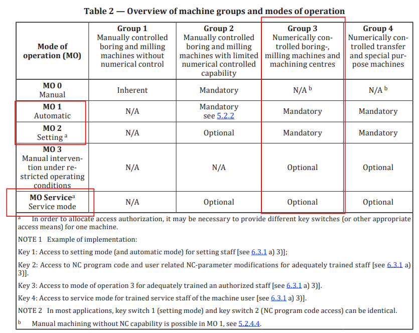
5.2.4 Mode of operation (MO)
Table 2 assigns the various, in this document standardised, modes of operation (MO) to the machine groups defined in this document (Group 1 to Group 4 machines). Standardized modes of operation may be:
– inherent: the MO is, due to technical limitations or lack of automatic control capability, the only possible mode of operation;
– mandatory: the MO shall be provided;
– optional: the MO may be provided; or
– not allowed: the MO shall not be provided to operate a machine belonging to a particular group.
5.2.4.3 Mode of operation 0: Manual (MO 0)
When MO 0 is selected, the following requirements apply.
a) If interlocked moveable guards are provided, the spindle rotation shall only be initiated manually by a control device provided for that purpose when these guards are closed. Movement of spindle with these guards open shall only be initiated and maintained with the enabling device actuated. Releasing the enabling device shall initiate a safety related stop function of the spindle rotation.
b) Axis feed movements shall be possible with interlocked moveable guards closed, and traverse movement speed shall be limited to 5 m/min. Axis feed movement with open interlocked moveable table guards shall be manually selectable and shall only be possible by hold-to-run control with 2 m/min limited speed.
c) Rapid traverse movements shall be manually selectable and shall only be possible by hold-to-run control.
d) With controllable power-driven feed axes, only one feed axis movement is allowed at a time. The spindle is permitted to rotate at the same time. Releasing the enabling device stops the spindle and feed motion initiated by a safety related stop function.
e) Applicable safety functions listed in Table J.17 (17.7, 17.8) shall be fulfilled.
5.2.4.4 Mode of operation 1: Automatic (MO 1)
MO 1 is the standard mode for production and can use the full performance of the machine. Manual movement of the machine axes and machining with running spindle drive is permitted with all safeguards active and guards closed. When MO 1 (automatic mode) is selected, the following conditions apply before the machine is started.
a) Moveable interlocked guards which give access to the work zone shall be closed and the protective devices shall be active to permit and maintain operation in automatic mode.
b) If whole body access to the hazardous area is possible, it shall be ensured that no persons are present in that area. If it cannot be ensured that persons can be seen from the position where the control devices for start/restart are located, requirements from 5.2.3.2 b) shall be fulfilled.
c) Where multiple main control cycle start devices are provided and the operators can therefore put each other in danger, only one shall be enabled at any time [see ISO 12100:2010, 6.2.11.8 e)]. If it is possible to start the same hazardous element by means of several controls, the control circuit shall be arranged that only one control is effective at any given time.
d) For start/restart in MO 1, the following requirements shall be fulfilled:
– the start/restart shall only be initiated from a control station where no hazard exists;
– protective devices relevant for this mode of operation including their safety related functions shall be properly arranged and active;
– the control device(s) for start/restart shall be located to allow a clear and unobstructed view to persons within the hazardous area.
Movements only associated with loading/unloading of tools/workpieces in MO 1 with guards open shall be possible with specific requirements stated in 5.2.5.1 (machine with tool magazine), 5.2.5.2 (machine with tool changer), 5.2.5.3 (machine with workpiece handling mechanism), 5.2.5.4 (machine with workpiece setting station) and 5.2.5.5 (machine with workpiece clamping mechanism).
5.2.4.5 Mode of operation 2: Setting (MO 2)
5.2.4.5.1 Basic specifications
MO 2 is a mode of operation which allows the operator to perform adjustments for the following machining process with movable interlocked guards open and/or protective devices suspended.
Assessment of the tool and workpiece position, e.g. by touching the workpiece with a probe or tool, is part of the setting mode.
When changing to MO 2 from any other MO, the working cycle shall firstly be interrupted and then access to the work zone can be enabled (e.g. by unlocking the interlocked guard with guard locking).
When a hold-to-run control device or electronic handwheel is used, single movement and spindle rotation shall be initiated and maintained only while the enabling device is actuated. Releasing the enabling device shall initiate a safety related stop function according Annex J. An enabling device is not required if the hold-to-run control device or electronic handwheel complies with the safety requirements according to 5.8.6.
When a manual data input (MDI) followed by command ‘cycle start’ is carried out, single axis and spindle movement shall be initiated and maintained only while the enabling device is actuated.
5.2.4.5.2 Range of functions
When any interlocked movable guard is open, and/or a protective device is suspended, hazardous powered machine movements shall only be permitted under the following conditions:
a) singular linear feed movements:
– shall be limited to a maximum of 2 m/min (for safety function, see Table J.2 (2.4), Table J.4 (4.10), Table J.18 (18.5)); or – the movement shall be in steps with a maximum increment of 10 mm;
b) for rotary axes (including workpiece and workholding spindle):
– peripheral speeds shall be limited to 15 m/min (for safety function, see Table J.2 (2.4), Table J.4 (4.10), Table J.18 (18.5); and – rotation speed shall be limited to 50 min−1 (see ISO 23125:2015, 5.2.4.4.1 d);
c) spindle speed shall be limited by its braking ability. After a stop command the spindle shall stand still within two revolutions without tool;
NOTE The number of two revolutions only refers to the displacement/angle covered by the deceleration procedure. Response time of the operator is not included, e.g. releasing the enabling device and control are not included.
d) the limits of rotational speed or axis feed movements or incremental distance [defined in a), b) and c) above] shall be monitored (see 5.8.7 and speed limit control in Table J.17 (17.3, 17.4). A stop shall be initiated when the speed limit is exceeded. The stop function of the movement shall be initiated by a safety related stop function according to Annex J;
e) unguarded swarf/chip conveyor movements shall only be initiated and maintained by a hold-to-run control device or an enabling device (first hand) in conjunction with a direction control (second hand) (see J.11.2 to J.11.3) but not in conjunction with feed axes and spindle movement;
f) for group 3 and group 4 machines only: Automatic tool- and workpiece changing mechanisms shall remain inhibited in case of pending operations within the work zone. Initiation of their automatic movement shall only be possible by reselection of MO 1. Manually controlled single movements of tool- and workpiece changing mechanisms are permitted in conjunction with an enabling device. Every movement shall be initiated by a start command. This can be achieved, for example, by MDI;
g) releasing the enabling device or the hold-to-run control device (see 5.8.6. a) shall initiate a safety related function according Annex J (marked as SF07-1 and SF07-2);
h) high pressure coolant shall be inhibited (see Table J.12).
5.2.4.6 Mode of operation 3: Manual intervention under restricted operating conditions (MO 3)
5.2.4.6.1 Basic specifications
MO 3 is an optional mode of operation, which permits the operation of the machine under manual or numerical control while guards are open and/or protective devices suspended.
This mode of operation is only permitted to group 3 and group 4 machines.
MO 3 may only be provided if the work task requires the opening of guard(s) and/or suspension of other protective devices.
Typical work tasks and applications for MO 3 with enabling device are the following:
- cleaning of workpiece, e.g. removal of chips to prevent surface scratching;
- CNC/NC program tests, especially cycle test with higher speeds of axes and/or spindles than permitted in MO 2 and direct observation with guard open is necessary;
- use of contact-type centring tools on hidden parts that cannot be seen from the front or on the back side of the workpiece, such as “edge finder”(observation of contact point by manual pulse handle feed in the rotated state).
NOTE: The limited range of functions (see 5.2.4.6.2) provided in MO 3 give a motivation to switch back to the higher performance of MO 1.
When selecting the modes of operation MO 1 or MO 3, the following sequences shall be implemented.
- The change from MO 1 to MO 3: First the operating conditions of MO 1 shall be reduced to those demanded in MO 3 and shall be monitored. Then the relevant safety requirements (e.g. the possibility for opening of guards or the interruption of protective devices) shall be allowed.
- The change from MO 3 to MO 1: First the higher safety requirements of MO 1 (e.g. movable guards closed, or light curtain activated) shall be activated, then the higher values of the operating conditions of MO 1 shall be allowed.
5.2.4.6.2 Range of functions
When any interlocked movable guard is open, and/or a protective device is suspended, hazardous powered machine movements shall only be permitted under the following conditions:
a) Singular linear axis feed movements shall be:
– limited to 5 m/min; or
– in steps with a maximum increment of 10 mm.
b) For rotary axes (including workpiece and workholding spindle):
– peripheral speeds shall be limited to 15 m/min; and
– rotation speed shall be limited to 50 min−1 [see ISO 23125:2015, 5.2.4.4.1 d)].
c) Spindle speed shall be limited by its braking ability. After a stop command the spindle shall stand still within five revolutions without tool.
NOTE The number of five revolutions only refers to the displacement/angle covered by the deceleration procedure. Response time of the operator is not included, e.g. releasing the enabling device and control are not included.
d) The limits of rotational speed or axis feed movements or incremental distance [as defined in a), b) and c)] shall be monitored [see 5.8.7 and speed limit control in Table J.17 (17.3, 17.4)].
e) Non-programmed movements shall be achieved as follows.
1) Spindle rotation shall be initiated by a spindle start control device together with an enabling device and maintained by the enabling device.
2) Axis movements shall be initiated and maintained by one of the following means:
– a hold-to-run device;
– an electronic handwheel; or
– manual data input (MDI) followed by cycle start together with an enabling device.
f) Execution of a program shall be initiated by a cycle start control device in conjunction with an enabling device and maintained by the enabling device.
g) Unguarded swarf/chip conveyor movements shall only be initiated and maintained by a hold-torun control device or an enabling device (first hand) in conjunction with a direction control (second hand) (see J.11.2 to J.11.3) but not in conjunction with feed axes and spindle movement.
h) Automatic tool and workpiece changing mechanisms shall remain inhibited in case of pending operations within the work zone. Initiation of their automatic movement shall only be possible by reselection of MO 1. Manually controlled single movements of tool and workpiece changing mechanisms are permitted in conjunction with an enabling device. Every movement shall be initiated by a start command. This can be achieved, for example, by MDI.
i) Releasing the enabling device or the hold-to-run control device (see 5.8.6 a) shall initiate a safety related function according Annex J (marked as SF07-1 and SF07-2).
j) high pressure coolant shall be inhibited (see Table J.12).
NOTE: In certain machining processes, e.g. with complex workpieces in single-part production, it can be necessary for the operator to observe the machining process when the guards are open and/or to take corrective action via the control device. Therefore, it is possible that the use of an enabling device over a longer period of time is not practicable for ergonomic reasons or that the setting of several parameters on the control device prevents the continuous actuation of the enabling device. In this case, an additional mode of operation can be provided using further protective measures. Due to the variety of possible machining processes that can require an additional operating mode, it is not possible within this document to standardise a corresponding operating mode. A technical report on this document with examples for the application of additional operating modes is being prepared.
5.2.4.7 Service mode (MO Service)
This mode of operation is intended for service tasks, such as calibration measurement, troubleshooting, diagnostic and checking of machine functions and performance. Therefore, MO Service enables restricted functionality of the machine or parts of it, at which guards of the individual work zone can be opened.
MO Service shall only be provided to service staff, who is trained by the manufacturer/supplier of the machine.
a) The following restrictions for automatic functionalities are required to provide this mode.
1) Simultaneous rotation of the spindle and axis motion is allowed only for measurement and calibration tasks.
2) Feed axis/axes can be moved under to following restrictions:
– with enabling device (PLr = d, Cat. 3) in conjunction with a hold-to-run control device;
– with enabling device (PLr = d, Cat. 3) in conjunction with a start command (PLr = b) and actuated override selection device; or
– if axes speed is lower than 15 m/min and safely limited in PLr = d, Cat. 3 (SLS) in conjunction with a start command (PLr = b) and actuated override selection device, an enabling device is not required.
3) Spindle rotation shall be initiated and maintained under the following restrictions:
– with an enabling device (PLr = d, Cat. 3) in conjunction with a hold-to-run control device; or
– with an enabling device (PLr = d, Cat. 3) in conjunction with a start command (PLr = b) and actuated override selection device.
4) Spindle speed shall be limited by its braking ability. After releasing the enabling device or the hold-to-run device the spindle shall stand still within five revolutions without tool.
NOTE: The number of five revolutions only refers to the displacement/angle covered by the deceleration procedure. Response time of the operator is not included, e.g. releasing the enabling device and control are not included.
5) If movement of tool changer and/or tool magazine is foreseen, automatic tool changing movements or tool magazine movement shall be initiated by a hold-to-run control device. It shall be possible to initiate the individual steps successively.
6) If the pressure of coolant is higher than 0.5 MPa an enabling device (PLr = d, Cat. 3) in conjunction with a permanently actuated hold-to-run control device is required to initiate and maintain the coolant supply.
7) Pneumatic or hydraulic movements of machine parts shall be initiated and maintained with an enabling device (PLr = d, Cat. 3) in conjunction with a permanently actuated hold-to-run device.
8) Tool measuring using laser-based methods are not permitted.
9) Movements of the chip conveyor shall be initiated and maintained with an enabling device (PLr = d, Cat. 3) in conjunction with a permanently actuated hold-to-run device.
b) More than one feed axis can be moved. c) Movements of automatic workpiece changing mechanisms shall, if applicable, be carried out with reduced speeds. The individual steps shall be initiated in succession.
Annex C
(informative)
Illustrative figures as examples of machines
C.1 Group 1 machines
See Figures C.1 and C.2.
C.2 Group 2 machines
See Figures C.3 and C.4.
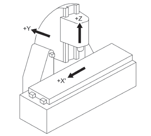
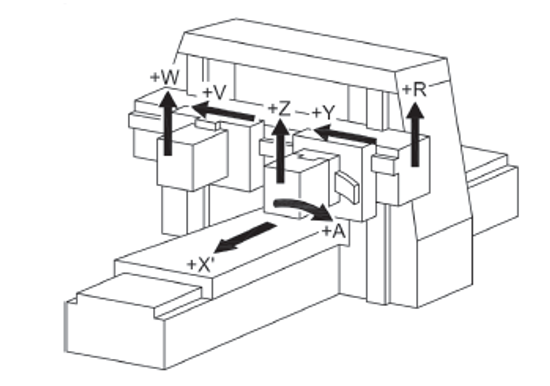
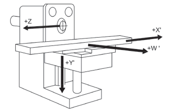
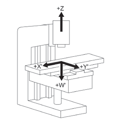
C.3 Group 3 machines
See Figures C.5, C.6 and C.7.
C.4 Group 4 machines
See Figures C.8 to C.13.
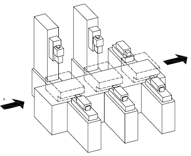
Figure C.8 – Transfer line (illustrated without guard)
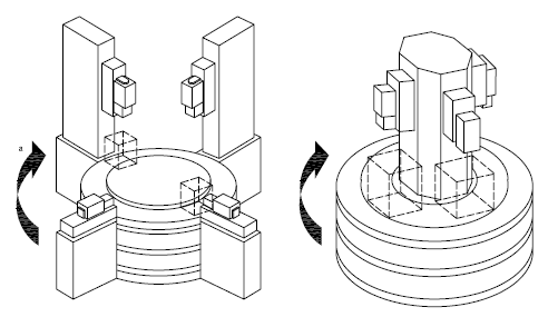
Figure C.9 – Rotary transfer machine (illustrated without guard)
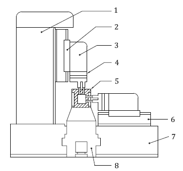
Figure C.10 – Side view of a processing unit of a transfer machine
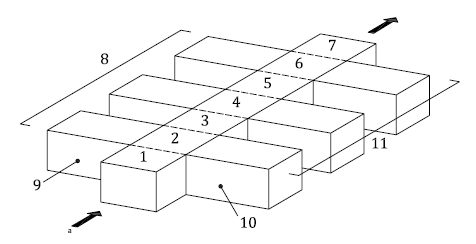
Figure C.11 – Substructure of a transfer machine
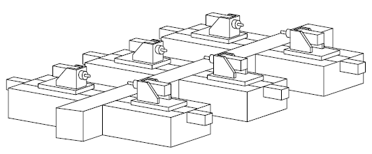
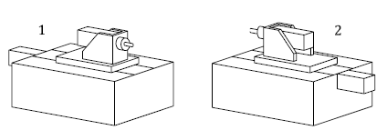
Figure C.13 – Typical units for transfer machines
Annex D
(informative)
Illustrative figures as examples of guards
D.1 Examples of adjustable guards for milling machined.es; Group 1 (manual machines)
See Figure D.1.
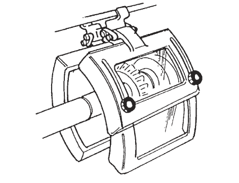
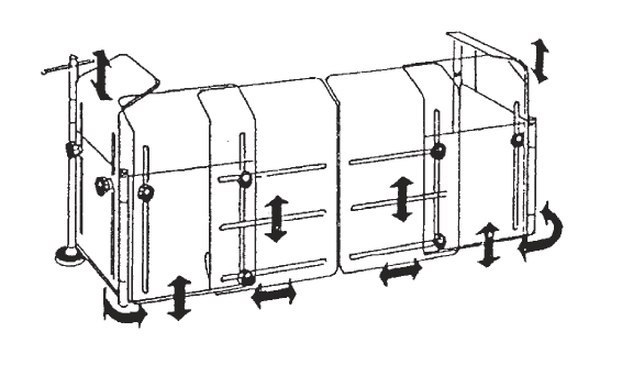
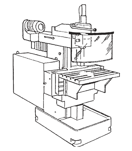
Figure D.1 – Examples of adjustable guards for manually controlled milling machines
D.2 Examples of guards for Group 2 machines (machines with limited NC capability)
See Figure D.2.
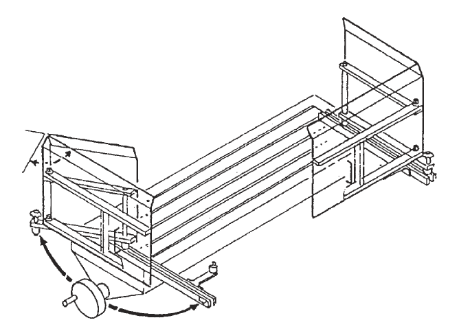
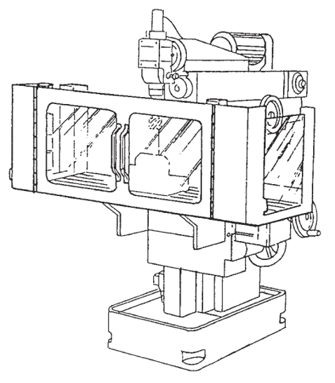
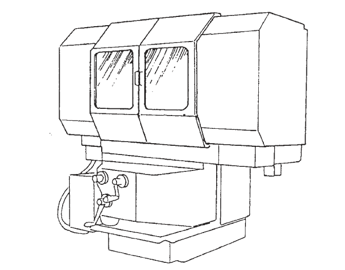
Figure D.2 – Examples of guards for Group 2 milling machines
D.3 Examples of guards for Group 3 machines (automatic machines)
See Figure D.3 to D.6.
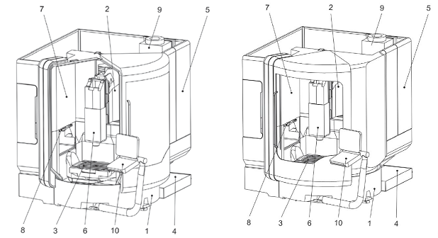
Key:
1 machine column (Y axis)
2 Y slide X slide (X axis)
3 slewing rotary table (SRT)/rigid table
4 cutting fluid system
5 machine enclosure
6 spindle head with motor spindle (Z axis)
7 electrical cubicle
8 tool change
9 cooling unit
10 control panel
Figure D.3 – Examples of guards for Group 3 machines (automatic machines)
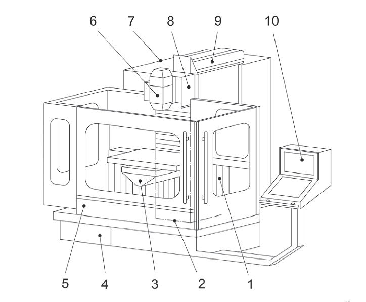
Figure D.4 – Example of interlocking guard(s) for automatic milling machines
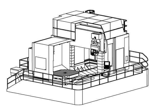
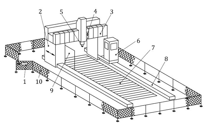
Figure D.6 – Example of large double column milling machine with moveable portal (gantry type), perimeter fencing and operator protection
D.4 Examples of guards for Group 4 (transfer and special purpose machines)
See Figure D.7 and D.8.
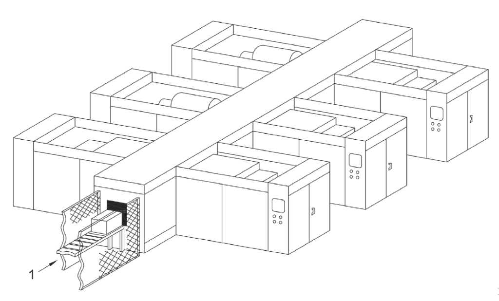
NOTE Machines are open on top, the middle transfer unit is covered on top.
Figure D.7 – Transfer line with guards arranged closely to the machine
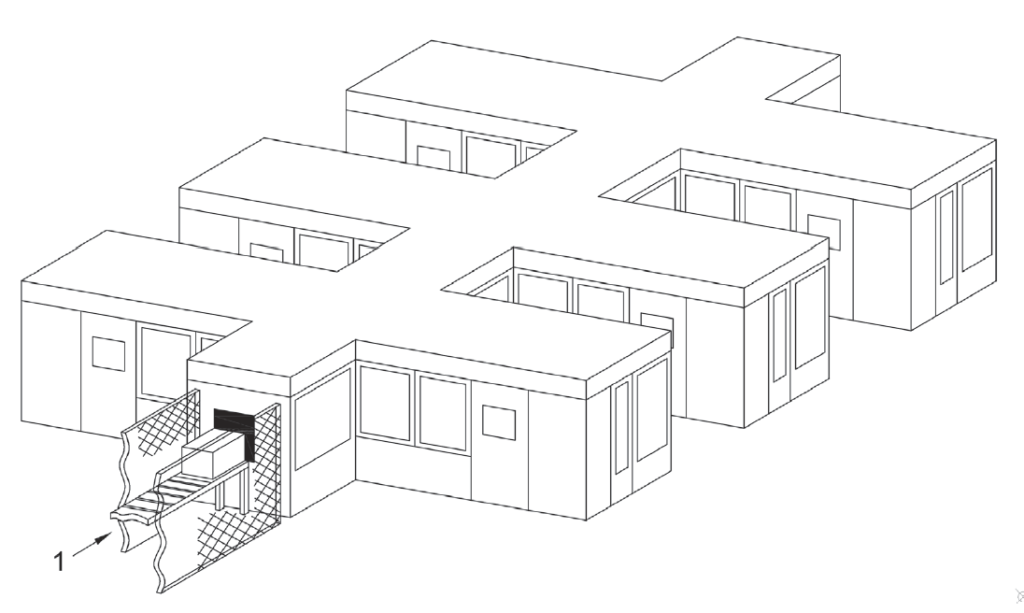
Figure D.8 – Fully enclosed transfer line
Comments are closed